Your shopping cart is empty!
 English
60AIM40 14poles Servo motor with 15bit FOC driver position closed loop, speed closed loop, CAN bus

Price: $96.60
Ex Tax: $96.60
Ex Tax: $96.60
3 or more $95.80
6 or more $94.00
6 or more $94.00
Qty:
- OR -
Add to Wish List
Add to Compare
Add to Compare
253060401 60AIM40 Servo Motor 14 poles with 15 bit FOC Driver, position closed loop, speed closed loop, CAN, All In Motor
AIM series servo motor is All In Motor, including the motor, encoder and driver. The driver is with open RS485 protocol and you can control the motor with PU (pusle) and DIR (direction).

AIM motors Specifications:
| AIM Series | ||||||||||||||||
| 42AIM10 | 42AIM15 | 42AIM30 | 57AIM15 | 57AIM30 | 60AIM25 | 60AIIM40 | ||||||||||
| Nominal voltage | V | 24 | 24-36 | 24-36 | 24-36 | 24-36 | 24-36 | 24-36 | ||||||||
| Nominal current | A | 1.6 | 2.2 | 4.4 | 2.2 | 4.4 | 7 | 7 | ||||||||
| Nominal torque | Nm | 0.33 | 0.48 | 0.96 | 0.48 | 0.96 | 2 | 3 | ||||||||
| Nominal Speed | rpm | 1000 | 1000 | 1000 | 1000 | 1000 | 1000 | 1000 | ||||||||
| Max Speed | rpm | 1500 | 1500 | 1500 | 1500 | 1500 | 1500 | 1500 | ||||||||
| Power | W | 35 | 50 | 100 | 50 | 100 | 200 | 200 | ||||||||
| Phase to phase resistance | Ω | 2.65 | 1.3 | 2.65 | 1.3 | |||||||||||
| Phase to phase inductance | mH | 1.1 | 0.5 | 1.1 | 0.5 | |||||||||||
| Weight | g | 320 | 340 | 500 | 360 | 560 | 650 | 800 | ||||||||
| Feedback | Absolute encoder, 32768 pulses per turn, 15 bits per turn | |||||||||||||||
| Cooling mode | Natural cooling | |||||||||||||||
| Max input pulse frequency | 500KHz | |||||||||||||||
| Pulse command mode | Pulse + DIR | |||||||||||||||
| Electronic gear ratio | 1-65535 : 1-65535 | |||||||||||||||
| Position sampling frequency | 2KHz | |||||||||||||||
| Communication | RS485(modbusRTU 19200,8,N,1) | |||||||||||||||
| Protection | Stall alarm | |||||||||||||||
| Max working temperature | C | 85 | ||||||||||||||
Drawings

AIM connector pins
Power Connector
| +24V | DC Power supply. Please note that If the power positive and negative terminals are reversed, the device might be damaged. +24V-36V |
| GND | Ground |
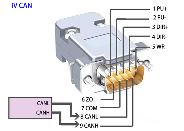
Communication DB9 Male connector
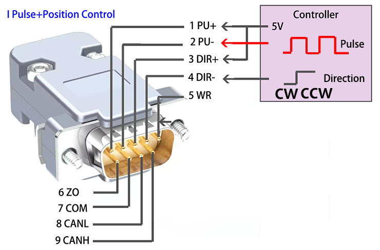
| 1 | PU+ | Blue color Pulse signal. The PU- is 0 to 0.5V. The pulse width need to be big than 1.2us. |
| 2 | PU- | Blue Black color Pulse signal. The PU+ is 3.3V to 5V. The pulse width need to be big than 1.2us. |
| 3 | DIR+ | Green color Direction signal. DIR+ is 4V to 5V, |
| 4 | DIR- | Green Black color Direction signal. DIR- is 0V to 5V, |
| 5 | WR+ | Red White color Alarm signal |
| 6 | ZO | Yellow color |
| 7 | COM | Black white color |
| 8 | CANL | Brown color CAN BUS |
| 9 | CANH | White color CAN BUS |
Can connection
Position and Direction Control
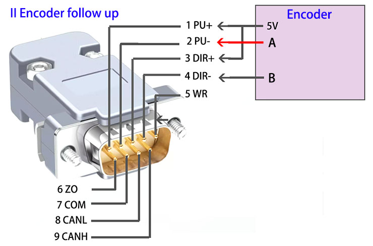
Encoder follow up connection
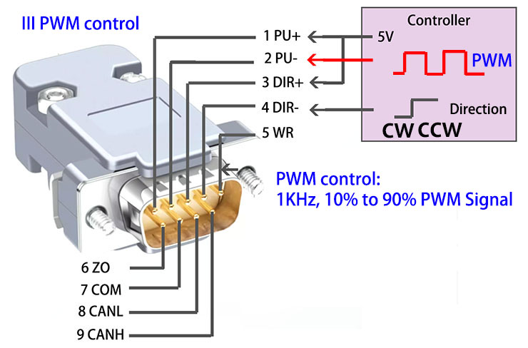
PWM control connection
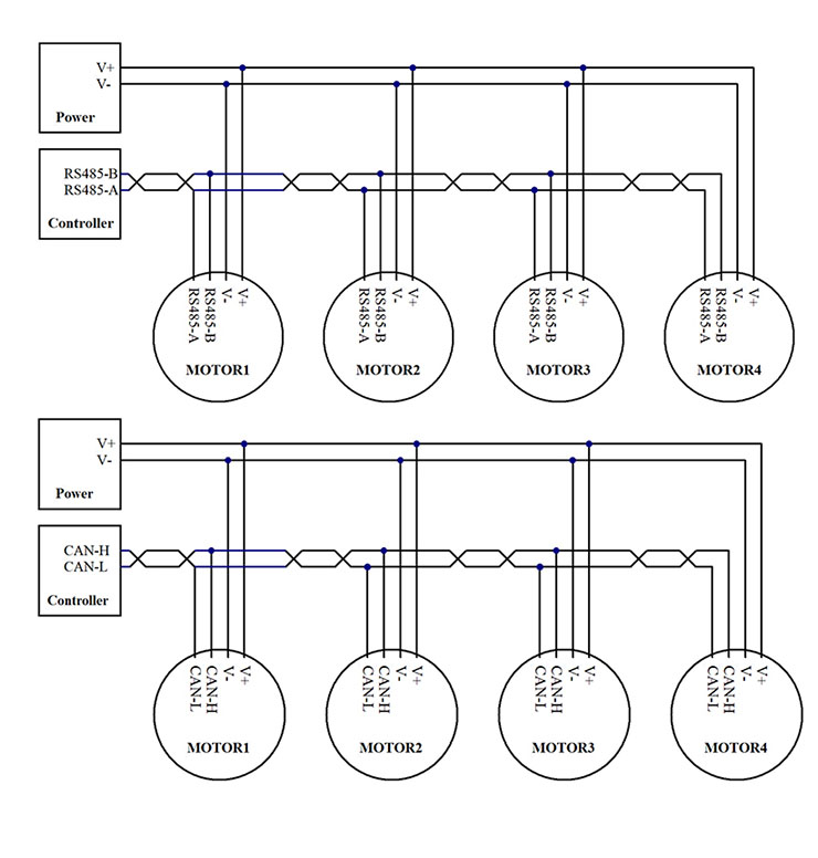
RS485 bus and CAN bus connection.
Copyright © 2003-2017 by SMC Powers Ltd. All Rights Reserved. Email: shop@smc-powers.com Skype:smc-power